Ground-penetrating radar
Making the invisible visible for a safe and efficient infrastructure
Ground-penetrating radar (GPR) provides comprehensive data on foundation soil and building components.
In contrast to conventional investigations using drills or probes, ground-penetrating radar provides continuous and comprehensive information about the terrain down to a depth of 3.5 meters. Ground-penetrating radar investigations thus complement and optimize conventional exploration methods by providing additional findings. The outcome is a comprehensive image of the foundation soil. Geotechnical reports prepared this way are more meaningful and reliable, guarding against unpleasant surprises while construction is underway. This optimizes the Design, bidding and implementation of projects in line with scheduling and budget requirements.
Dr. Daniela Hofmann
Environmental & Geo-Services
Haferwende 7
28357 Bremen
Germany
Downloads
What is ground-penetrating radar?
Ground-penetrating radar is a non-destructive geophysical survey method that is used to image the foundation soil. It works by transmitting pulses of electromagnetic radiation into the ground. When these pulses encounter materials with different properties, they are reflected back and detected by an antenna. By recording how long it takes for these reflections to return, the system can map the depth and shape of structures in the subsoil.
Benefits of the solution
- Non-destructive use in subsoil or for structures.
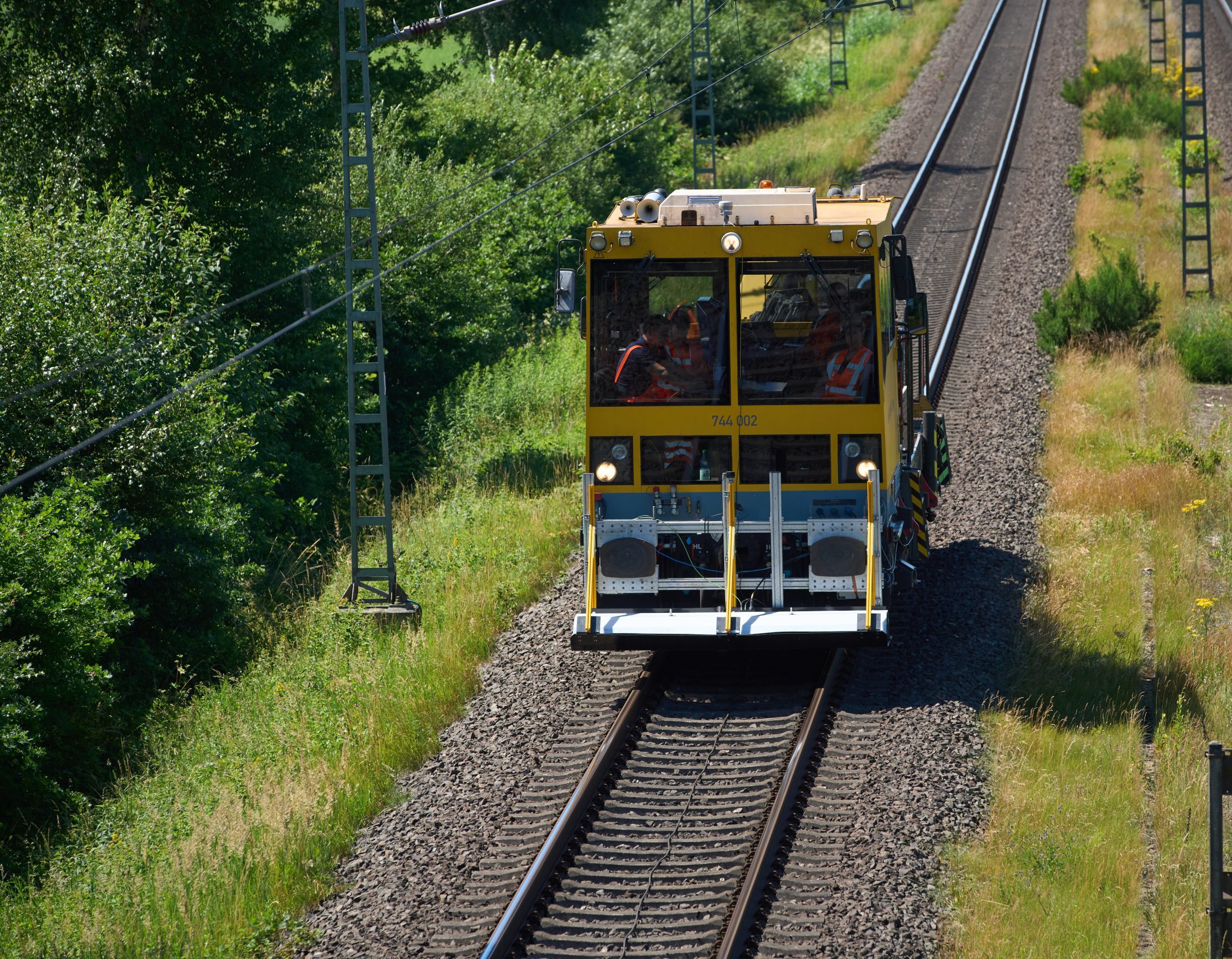
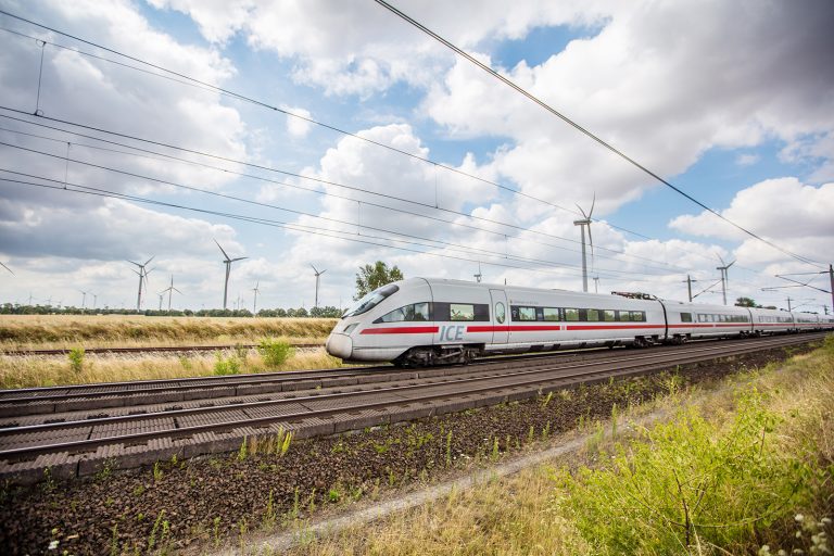
- Efficient data collection even during ongoing operations: High-resolution measurements can even be made during measurement runs at speeds of up to 120 km/h (for example, with the 360° Multisensor Platform).
- Digital integration into planning processes: The data acquired can be seamlessly integrated into BIM models and support data-driven design, construction preparation and maintenance.
- Early risk detection: Precise and extensive advance knowledge about the foundation soil enables optimal planning and bidding for construction services and ensures construction will proceed smoothly (lowering the risk of having to add to or pause work during the construction phase).
- Optimized geotechnical investigation: With a detailed understanding of the foundation soil, geotechnical probing investigations can be more precisely planned and their number optimized.
- OOOO0kilometers of track data has already been recorded
- OOO0platforms at 74 stations have already been surveyed
Uses in infrastructure design
- Capturing and providing the data that forms the basis for Building Information Modeling.
- Capturing and providing the data that forms the basis for condition-based or predictive maintenance, e.g. for permanent way improvements.
- Can be used in quality control: target-performance comparison to check whether structures conform to plans.
Questions & Answers
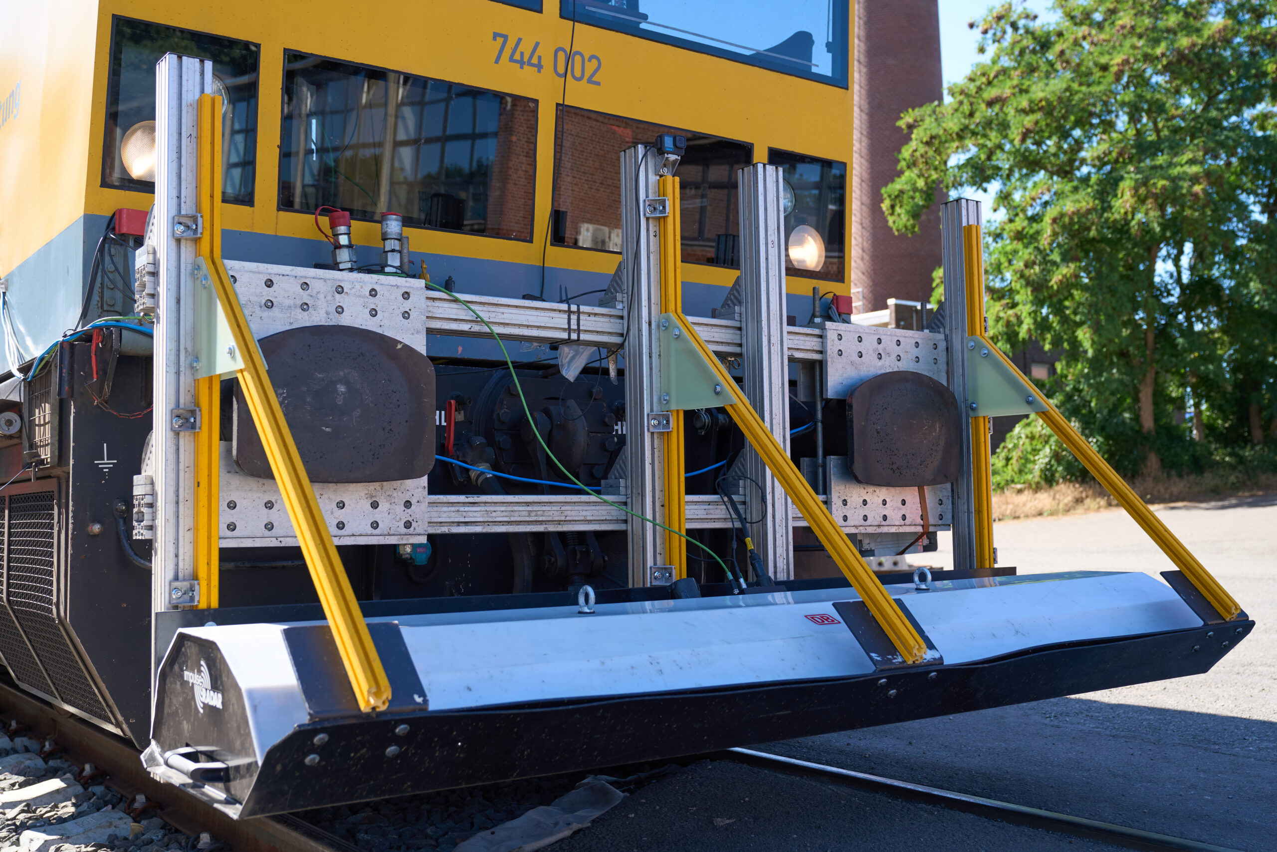
Ground-penetrating radar works by transmitting pulses of electromagnetic radiation into the foundation soil and measuring how long it takes for the signals to be reflected back. Based on how much time this takes, the depth (if the material parameters are known) and position of underground structures can be precisely determined. Additional geotechnical surveys must then be conducted. DB Engineering & Consulting uses state-of-the-art ground-penetrating radar systems and antennas in the 270 MHz and 2,000 MHz frequency ranges.
The system can detect a wide range of objects and materials, including:
- Pipes, cables, conduits and cable pathways
- Foundations, shaft structures and inhomogeneities
- Layer boundaries in the subsoil
- Reinforcement layers, tendons, building geometry and inhomogeneities (e.g. gravel pockets)
This makes the method ideal for structural, track and route analyses in infrastructure projects.
The measuring range depends on the soil properties and the frequency used.
Under optimal conditions – in dry soils, for example – depths of four meters or more (even 20 to 30 m in dry sand) are achievable.
In conductive soils (e.g. clay), the range is typically between one and three meters.
All measurement results are processed digitally and can be exported in formats such as BIM-compatible point clouds, DXF, IFC or LAS files. The data can be integrated directly into planning software or digital twins. This creates seamless transitions between measurement, design and maintenance management.
Ground-penetrating radar is used in various fields of infrastructure, including the following:
- Rail and road infrastructure (to analyze the subgrade and detect pipes, cables and conduits)
- Bridges and tunnels (for structural diagnostics)
Industrial and electrical power systems (to determine the position of pipes, cables and conduits)
Thanks to its portable design, DB Engineering & Consulting can efficiently take measurements even over long distances.
Yes. Ground-penetrating radar data is integrated directly into the X2BIM data platform and can be combined with results from multisensor or drone surveys. This creates a complete, digital image of the infrastructure that provides the basis for precise analyses, simulations, and maintenance strategies. Ground-penetrating radar is also part of our Structure 360° solution and optimized geotechnical investigation.
In contrast to drilling or excavation, ground-penetrating radar is completely non-destructive.
It enables faster data acquisition with less disruption to the infrastructure, thereby minimizing the duration of work windows and reducing costs.
Furthermore, the measurement results provide digital data that can be used straight away for planning and design.
Yes. DB Engineering & Consulting uses specially adapted measuring systems that can also be used during ongoing rail operations.
Measurements are taken either directly on the track or on vehicles traveling at speeds of up to 120 km/h – without interrupting operations.
The accuracy depends on the ground conditions and the antenna frequency.
As a rule, the measurement results are accurate in the centimeter range; under optimal conditions, in the sub-centimeter range.
DB Engineering & Consulting also validates the results through calibration measurements and data synchronization with other sensors.
The duration depends on the area and the data resolution.
A route survey covering several kilometers can be carried out in a matter of hours. The data is then processed and interpreted using (partially) automated methods, and initial results are generally available within one working day.
Yes. DB Engineering & Consulting has compact measuring systems that can also be used in urban areas, in tunnels or on bridges.
This means that the technology is suitable not only for large-scale projects, but also for pipe/cable/conduit analyses or structure analyses in built-up urban areas.
All measurement results are saved in a digital project environment and can be accessed via the X2BIM data platform.
Customers have access to 3D models, point clouds and visualizations that they can use at any time for maintenance, planning, design, or documentation.
The surveys are conducted by certified specialist engineers and geophysical specialists.
DB Engineering & Consulting adheres to national and European standards (e.g. DIN EN 302066, GL 836 and DIN 4020) and ensures the greatest possible measuring accuracy through internal quality assurance and regular calibration.
Yes. Using ground-penetrating radar data in conjunction with BIM and carbon footprint assessment methods provides an efficient way to evaluate the material conditions and life cycles of structures (see also BIM4LCA).
This supports sustainable infrastructure design and contributes to the optimization of maintenance strategies.
The choice of resolution (scan density) depends on the specific survey objective and the size of the structures to be detected. By default, 20 scans per meter are recorded, corresponding to a trace spacing of 5 cm.
A lower scan density can result in loss of information, as smaller objects may not be adequately detected. For surveys requiring a high level of detail, the scan density can be increased to up to 200 scans per meter. This corresponds to a trace spacing of 0.5 cm and allows the subsoil to be mapped in significantly greater detail.
The antenna frequency is selected based on the specific survey objective and the requirements for penetration depth and resolution. In principle, there is a trade-off between these two parameters: As the frequency increases, the resolution improves, while the achievable penetration depth decreases.
High-frequency antennas (e.g. 1,000 MHz):
High-frequency antennas provide detailed imaging of the shallow subsoil and achieve penetration depths of up to approximately 1.5 m. Due to their high resolution, they are particularly suitable for investigating layer structures, detecting reinforcements, and for structural inspection and quality control applications.
Low-frequency antennas (e.g. 400 MHz):
Depending on the subsoil conditions, low-frequency antennas achieve penetration depths of up to approximately 3.5 m. However, the lower frequency is accompanied by reduced resolution. They are therefore primarily used for subsoil investigations and for detecting pipes, cables and conduits, foundations, voids, and other deeper structures.
Depending on the application, GPR antennas with frequencies ranging from approximately 200 MHz to 2,000 MHz are available. Surveys can be carried out at depths ranging from approximately 0.3 m to 10 m, subject to the material properties of the subsoil. By selecting a suitable antenna frequency, the measurement system can be optimally tailored to the specific survey objective.