It records and documents obstacles concealed in the subsoil (pipes, foundations etc.) and risks in the composition of the subsoil (e.g. peat lenses or rock) in advance. This can obviate the need for expensive follow-up studies, because exposures can be made at the specific sites of anomalies in the subsurface. Ground-penetrating radar can also examine the condition of structures. The focus, for instance, is on identifying the reinforcement layer and assessing the concrete cover. GPR can also detect features like gravel pockets, moisture and cavities.
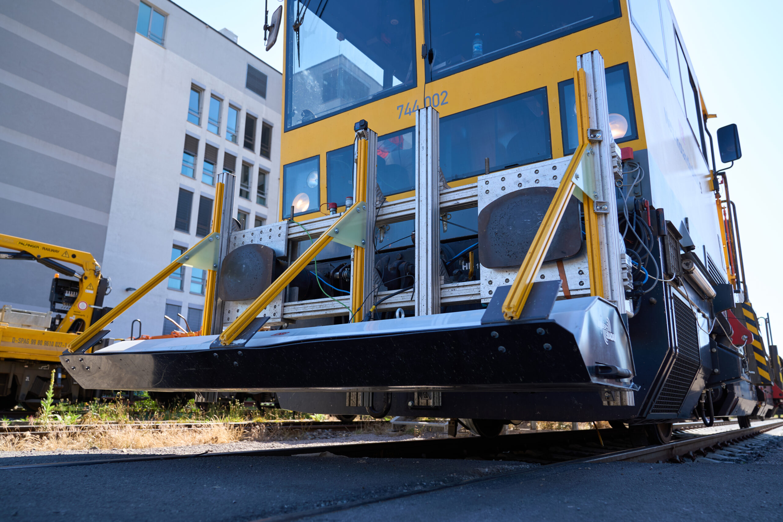
GPR is a non-destructive survey method that is used to image the subsoil. It works by transmitting pulses of electromagnetic radiation into the subsoil. At the boundary between different materials, the signal is (partially) reflected and recorded by a receiver. The propagation speed depends on the material under investigation. An antenna moves over the surface, continuously scanning the subsoil. Depending on the resolution available, a measured value is generated at certain intervals (scans/m). A radargram, that is, a vertical section of the soil along a measured line, is generated by stringing the individual measured values together.
- Depends on the project requirements specification
- High-frequency antennas (e.g. 1,000 MHz)
- Penetration depth up to approx. 1.5 m
- Higher resolution in the near-surface zone
- Used for detecting the configuration, reinforcement etc.
- Used in quality control
- Low-frequency antennas (e.g. 400 MHz)
- Penetration depth up to approx. 4 m
- Lower resolution in the near-surface zone
- Used for detecting the subsoil
- Used for detecting pipes, structures etc.
- There are antennas with measuring frequencies between 2,000 MHz and 200 MHz, with penetration depths between 30 cm and 10 m, which can be used depending on the project requirements specification.
- Visibility of details depends on the project requirements specification
- 20 scans/m are standard (measured value every 5 cm)
- Loss of information at low resolution at e.g. 5 scans/m (measured value every 20 cm)
- Up to 200 scans/m are possible (measured value every 0.5 cm)
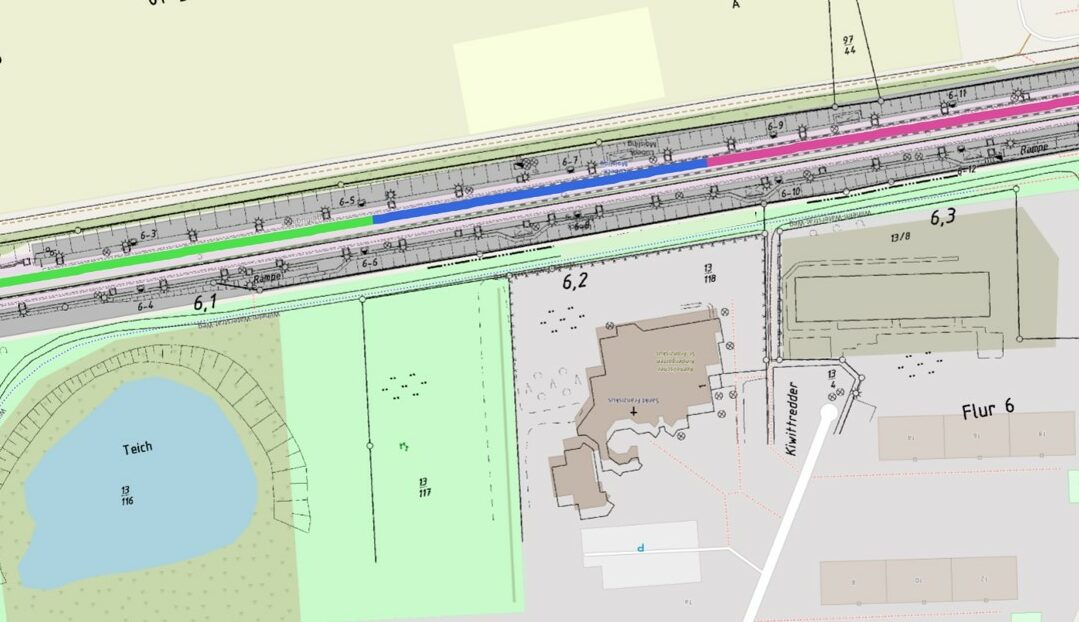
- Minimizing risks: precise and extensive advance knowledge about building terrain enables optimal planning and bidding for construction services and ensures construction will proceed smoothly (lowering the risk of having to add to or pause work during the construction phase)
- Non-destructive use
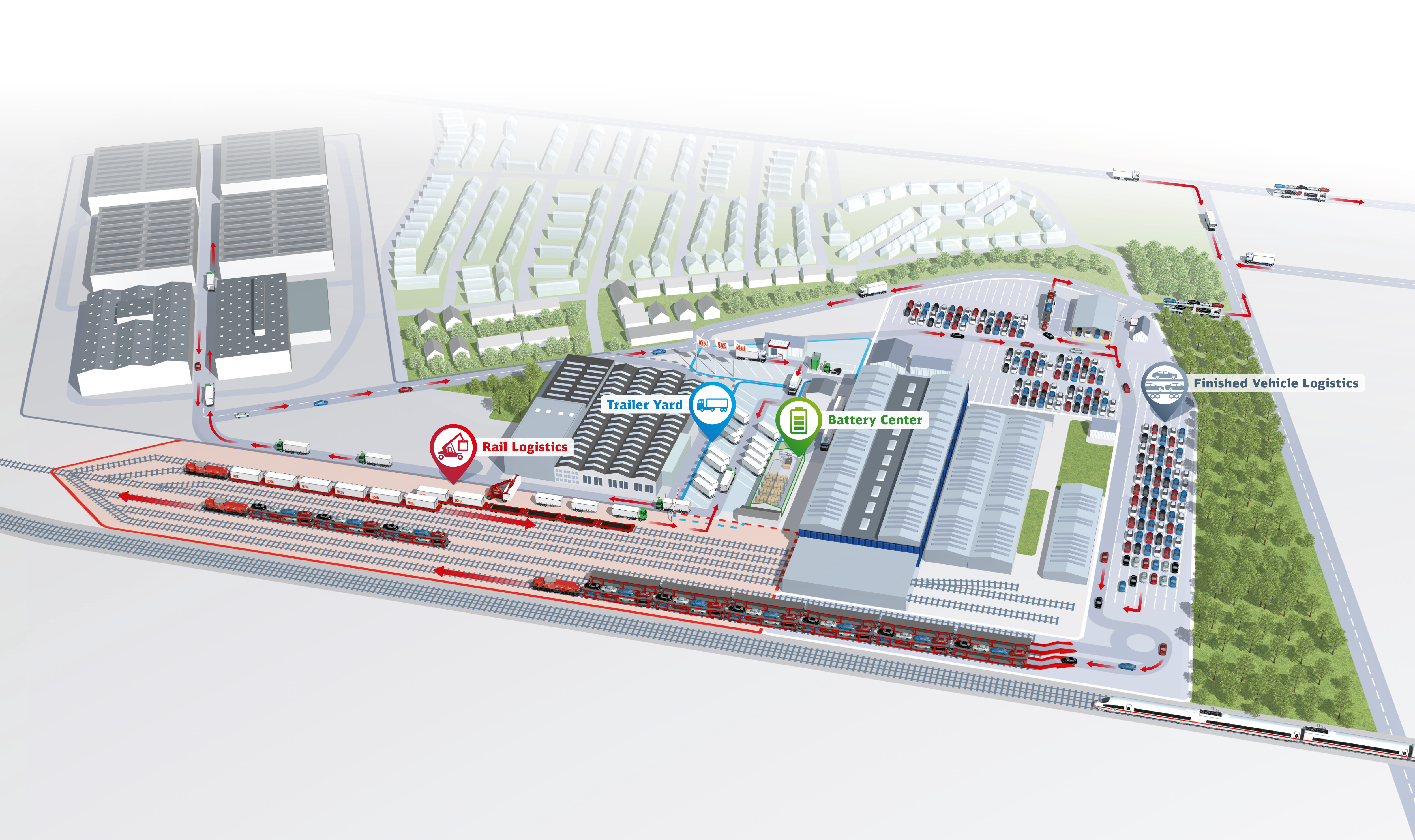
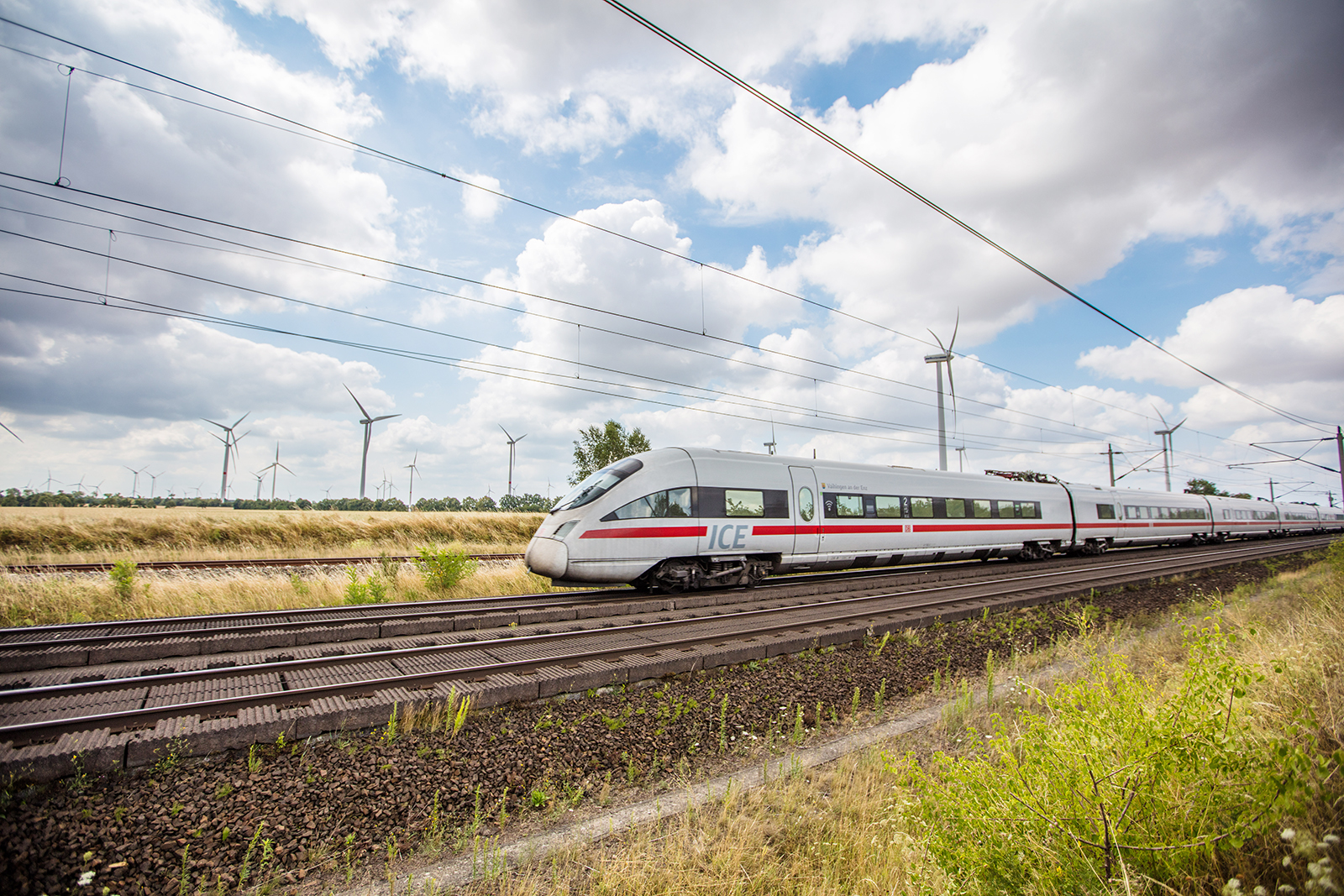
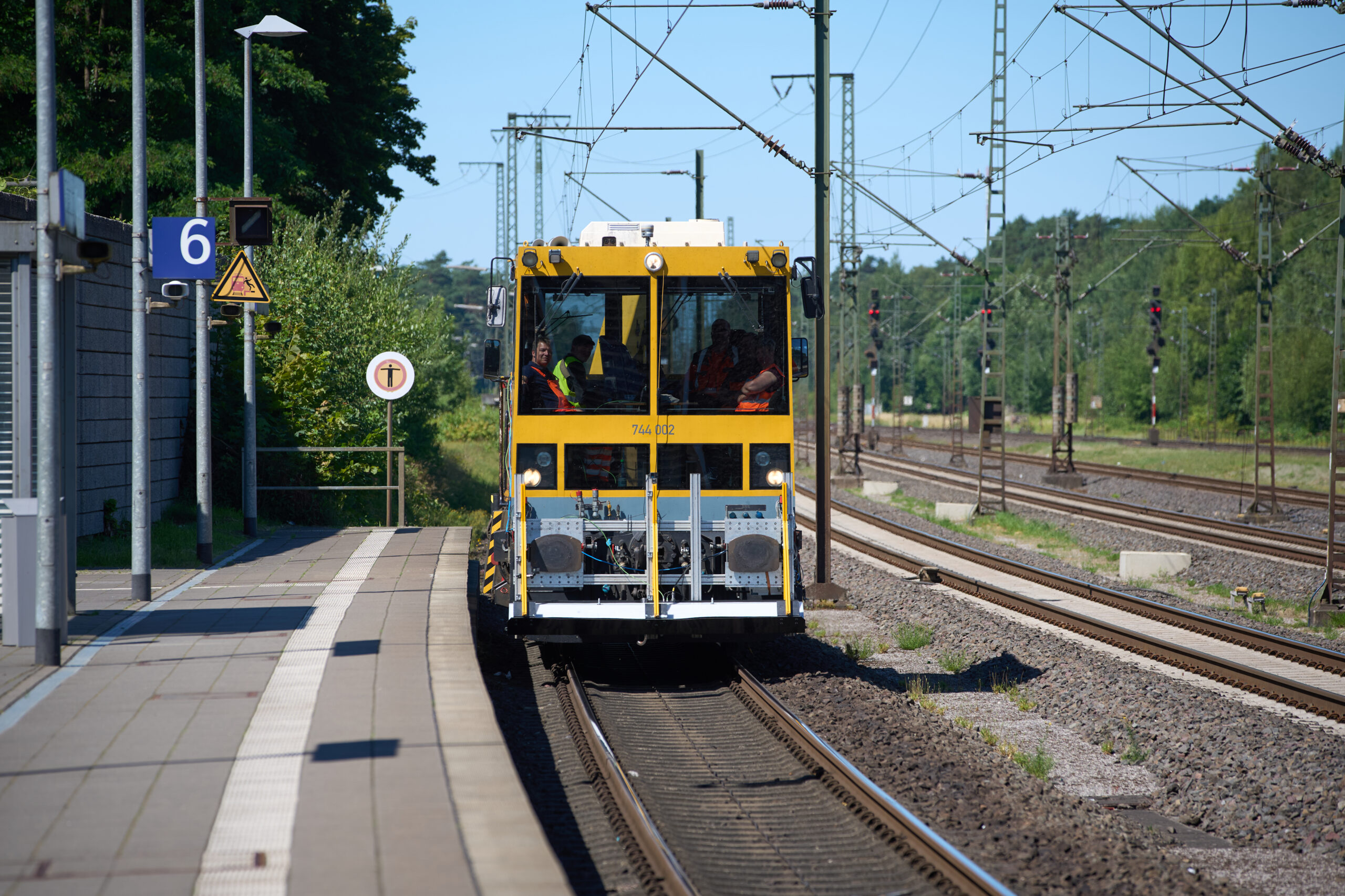
- No operational restrictions of rail or road traffic, as measurements can be made during regular operation
- Combining GPR with other methods (scanner systems and line scan cameras etc.) and data (e.g. track geometry data) yields a complete 3D image of the object under investigation, which serves as the basis for the management of infrastructure facilities.
- Determining and providing the data that forms the basis for Building Information Modeling (BIM)
- Determining and providing the data that forms the basis for condition-based or predictive maintenance, e.g. for permanent way improvements
- Can be used in quality control: target-performance comparison to check whether structures conform to plans
- Imaging and documenting the condition of terrain and structures
- Detecting cavities and determining the location of reinforcement, pipes and foundations
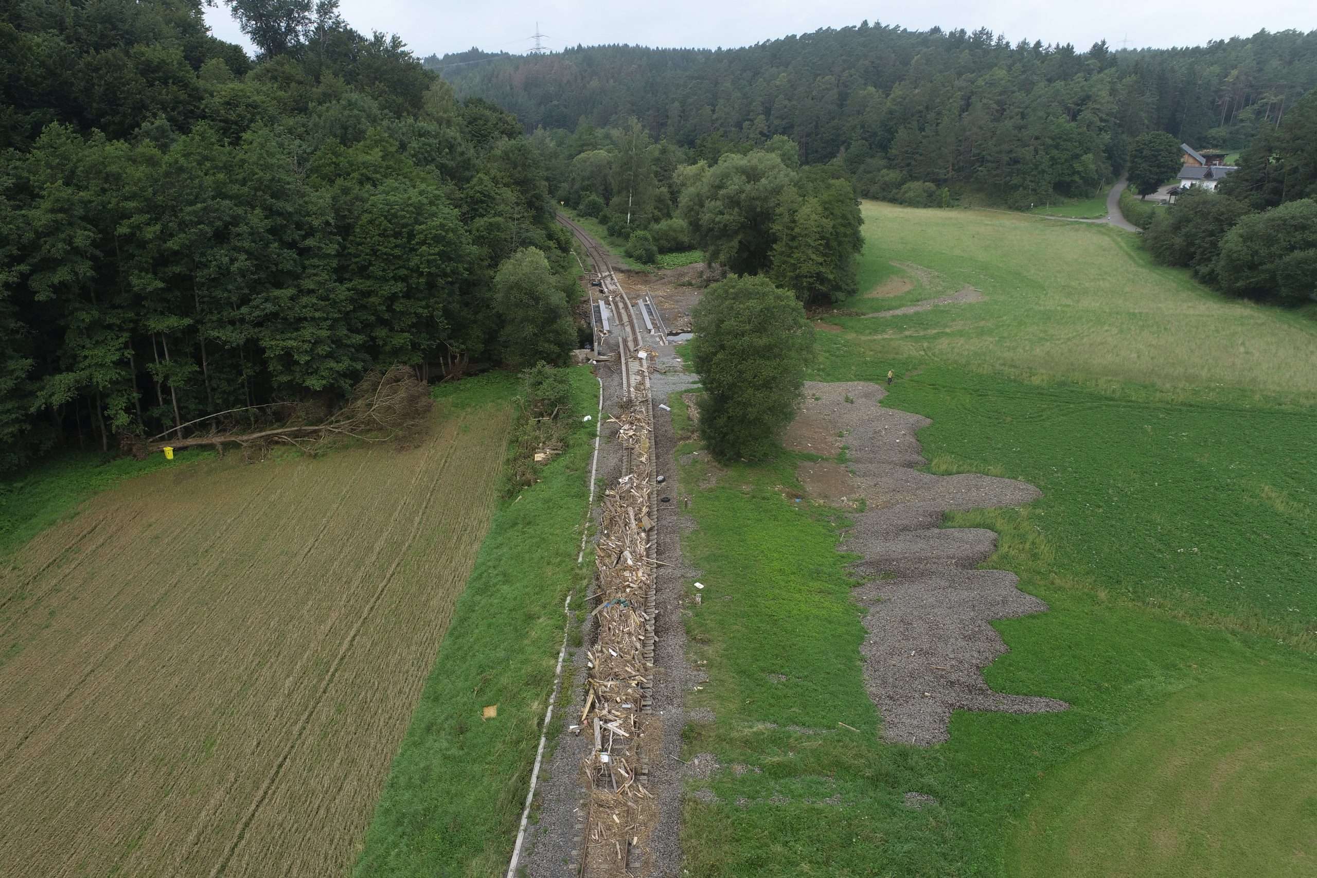
- Detecting anomalies and risks such as peat lenses, areas of mud, hard core, rock horizons, ballast fouling, moisture etc.
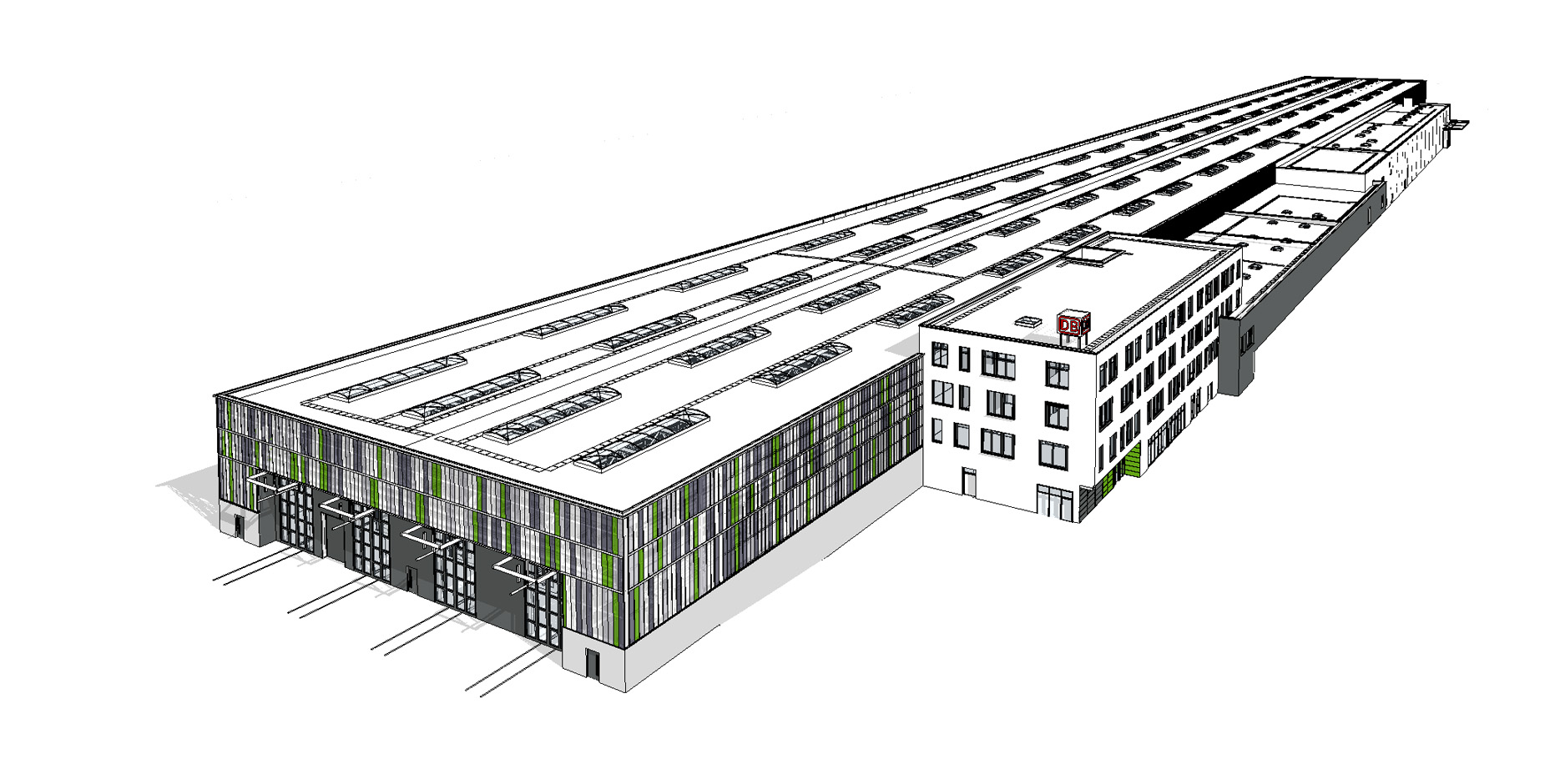
- Can be used on rails, roads, platforms, tunnels, bridges, dikes, industrial areas, sewers and in buildings
- Can explore up to 4 m deep
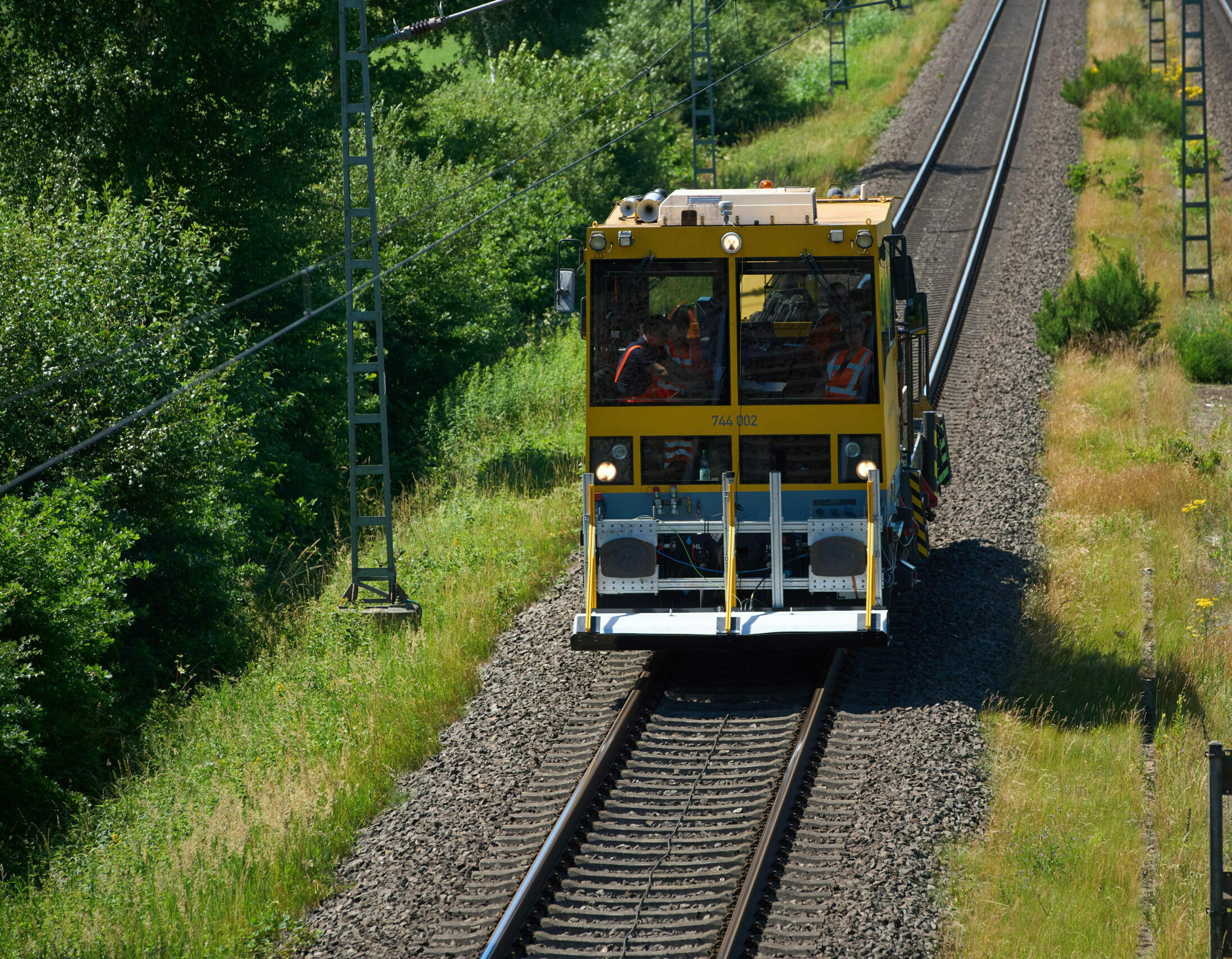
- Can measure at a speed of up to 100 km/h with a resolution of 20 scans/m, i.e. one measuring point every 5 cm (higher resolutions are possible at lower speeds)
There is currently a great need for exploration due to a lack of information about the subsoil. Conventional exploratory procedures are very time-consuming and time pressure and few time windows for maintenance-of-way work windows, e.g. for the General overhauls of high-performance corridors, can cause further delays, additional costs and planning uncertainties.
Our georadar experience in close coordination with geotechnical engineering experts:
- enable continuous and area-wide recording of the subsoil during track operation without maintenance-of-way work windows (track scan) for an efficient and guideline-compliant planning basis.
- Identify weak points and drill holes directly where there is a need for more detailed exploration.
Optimized geotechnical investigation offers many advantages:
- Time savings: fewer necessary boreholes mean shorter maintenance-of-way work windows and therefore faster project completion.
- Cost reduction: The targeted drilling strategy significantly reduces exploration costs.
- Higher quality: The combination of geotechnical engineering and georadar enables a more precise analysis of the subsoil and thus greater planning reliability.